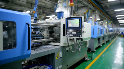
Choosing Golf Cart Plastic Injection Molding is not just a matter of selecting a resin and requesting a quote. A dashboard panel, seat base, and battery cover face different loads, temperatures, and weather exposure. The right process begins with the part’s job. Small details matter. Will the component sit in direct sun? Could it be struck by luggage, washed often, or exposed to cleaning products? Those answers help narrow material options and clarify what the mold must produce.
A reliable supplier should explain resin choices, draft angles, wall thickness, gate locations, and expected tooling life in plain language. Ask for examples of similar parts and how they handled warpage, surface finish, and dimensional checks. A glossy sample can look convincing while hiding weak ribs or poor fit. Fit comes first. Request prototypes or trial parts, then check them on the actual cart. Test exposed components under realistic heat, moisture, and handling conditions. One uncomfortable truth: early testing can reveal that a preferred design is too costly or difficult to mold. That is useful, even if it means revising the part.
A named expert’s exact quotation should be verified against a reliable source; none was provided for this topic, so attributing invented words would be misleading. Instead, use this practical guide to compare suppliers by documented experience, transparent process controls, and clear answers about trade-offs. The best choice is not automatically the cheapest mold or the strongest resin. It is the solution that fits the cart, production volume, operating environment, and maintenance needs—with evidence to support those decisions.
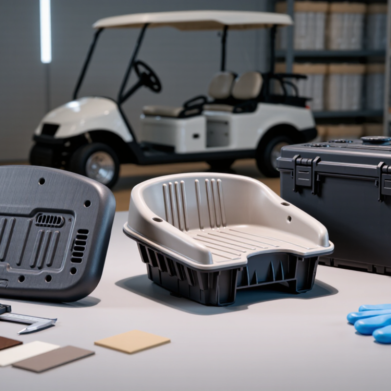
How to Choose Golf Cart Plastic Injection Molding?
Define Component Loads, UV Exposure, and Impact Risks Before Design
Start with the job each molded part must do. A roof panel faces wind pressure and repeated vibration; a seat base carries concentrated weight around its mounting points. Record load direction, support spacing, and expected service cycles before selecting a resin. The U.S. EPA’s UV Index guidance classifies readings of 11 or higher as extreme. For carts used in exposed locations, that is a useful warning to assess sunlight and heat together, not a guarantee of a specific service life. Check local exposure using the National Renewable Energy Laboratory’s National Solar Radiation Database. It provides hourly solar data for comparing operating environments.
Impacts are often local. A stone may strike a fender, while a dropped tool can hit a battery cover. Test representative molded samples, including corners, ribs, and fastener areas. ASTM D256 measures notched Izod impact resistance; ASTM G154 provides a controlled fluorescent-UV exposure method. These tests help compare candidate materials, but neither recreates every real-world condition. That limitation matters.
Specify UV exposure, impact temperature, and load cases before tooling. Ask suppliers for test conditions and actual results, not just a resin name or a single strength value. A thicker wall may improve stiffness, yet it can add weight and create uneven cooling. I would revisit that trade-off with prototype parts after outdoor exposure; lab results rarely tell the whole story.
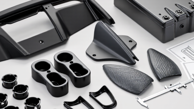
For golf cart plastic parts, shrinkage can change panel fit, screw alignment, and the gap around a headlamp opening. PP typically has a mold shrinkage range of 1.0–2.5%, while ABS is often around 0.4–0.7%. These are starting ranges, not guaranteed outcomes; resin grade, wall thickness, mold temperature, and packing pressure all affect the finished dimensions. That matters. On a long fender, even a small variation can shift an edge enough to create uneven gaps.
PP may suit flexible panels and impact-exposed parts, but its higher shrinkage calls for careful allowance in the mold design. ABS generally shrinks less, which can help with dimensional consistency on dashboards or trim with visible seams. Still, lower shrinkage does not automatically mean a better part. Ribs, thick corners, and uneven cooling can cause warpage in either material. It is tempting to choose from the percentage alone. I would also check the resin supplier’s data sheet, review the part’s critical dimensions, and trial the actual mold. A simple test piece may reveal more than a tidy estimate.
Typical mold shrinkage ranges: PP, 1.0–2.5%; ABS, 0.4–0.7%.
PP generally has a higher and wider shrinkage range than ABS, so dimensions may require more allowance during mold design. Actual shrinkage varies with material grade, part geometry, and processing conditions; validate the selected resin and tooling with supplier data and part testing.
Choosing plastic for a golf cart body panel means checking how it stretches and how it handles sudden blows. ASTM D638 measures tensile properties, including strength and elongation, using a shaped specimen pulled until it deforms or breaks. These results help compare candidate materials for parts exposed to vibration, fasteners, and repeated handling.
ASTM D256 evaluates notched impact resistance with a pendulum striking a specimen. That notch matters: it creates a stress point similar to a small cut or sharp corner. For a cart fender, an impact result can help assess resistance to cracking from a kicked-up stone or an accidental bump. Test temperature also matters, since some plastics become less impact-resistant in cold conditions. Small details change results.
Ask the molder for test reports tied to the proposed resin and molding conditions, not just a general data sheet. Compare specimens made with consistent thickness, conditioning, and test settings. D638 and D256 provide useful evidence, but neither predicts every failure in a finished part. A coupon is not a cart body. Mold flow, ribs, weld lines, mounting holes, and uneven wall thickness can change performance. I would also inspect molded parts and test them under realistic service conditions; that extra step can reveal weaknesses the laboratory numbers miss.
How to Choose Golf Cart Plastic Injection Molding?
Specify UV and Flammability Testing with ASTM G154 and UL 94
Golf cart plastics face sunlight, rain, heat, and repeated handling. Fenders may fade, while dashboard panels can become brittle after prolonged exposure. Specify testing early, before finalizing the resin, color, and wall thickness.
ASTM G154 describes accelerated exposure using fluorescent UV lamps and moisture. It does not provide one universal pass-or-fail requirement. Agree on the lamp type, exposure cycle, duration, and acceptance criteria. Then inspect molded samples for color change, cracking, warping, and surface chalking. A flat coupon is useful, but it can flatter the design; part shape and molding conditions matter.
UL 94 evaluates the burning behavior of plastic specimens under defined conditions. Classifications depend on factors such as specimen thickness and orientation, so request evidence for the selected material grade and thickness. A rating alone does not prove that a finished golf cart component will perform safely in every installation. Check whether the part sits near wiring, electrical enclosures, or other heat sources.
Tips: Test production-representative parts when possible. Record resin grade, color, thickness, and test conditions. Small details are easy to overlook, and they can change results. Discuss any failed criterion with the testing laboratory before revising the material or mold.
| Part or Use Area | Material Selection Considerations | UV Exposure Specification | Flammability Specification | Project Acceptance Criteria |
|---|---|---|---|---|
| Exterior body panels and fenders | Consider an outdoor-grade, UV-stabilized thermoplastic such as ASA or a suitable UV-stabilized PC/ABS grade. Confirm impact performance, chemical exposure, color, and molding requirements for the specific part. | Use ASTM G154 fluorescent UV exposure. A commonly specified example cycle is 8 hours of UVA-340 exposure at 60 °C followed by 4 hours of condensation at 50 °C. Agree on the lamp, cycle, total exposure duration, and specimen preparation before testing. | Specify a UL 94 classification only when required by the part’s location, applicable regulations, or customer risk assessment. State the required classification and tested material thickness. | Set project-specific limits before testing—for example, a maximum color change (ΔE) and minimum retained impact strength. ASTM G154 defines exposure practices; it does not set universal pass/fail limits for color or durability. |
| Roof, roof supports, and sun-exposed trim | Prioritize UV stabilization, heat resistance, stiffness, and resistance to weathering. Validate the selected resin and color formulation in the actual molded thickness. | Use the agreed ASTM G154 cycle and document total exposure hours, irradiance control, temperature, and condensation conditions. Inspect exposed specimens against unexposed controls. | Do not assume a flame rating from the resin family alone. If a rating is needed, obtain UL 94 test evidence for the exact formulation and thickness relevant to the part. | Define acceptable appearance changes and post-exposure mechanical properties based on the part’s function. Project limits are design requirements, not ASTM G154 requirements. |
| Dashboard, instrument-panel components, and interior trim | Choose a resin based on impact needs, heat exposure, surface finish, chemical contact, and dimensional stability. Interior parts may still receive substantial sunlight through glazing. | Specify ASTM G154 exposure when sunlight-related fading, chalking, or embrittlement is a concern. Select and record a cycle appropriate to the intended evaluation; different cycles can produce different results. | Where required, specify the applicable UL 94 category: HB for horizontal burning evaluation, or V-0, V-1, or V-2 for vertical burning evaluation. Confirm the classification at the relevant thickness. | Record visual observations and any agreed color or property measurements. UL 94 classification is tied to the tested material construction and thickness; it is not a general rating for every molded part. |
| Battery enclosure or electrical-component housing | Evaluate electrical, thermal, chemical, impact, and enclosure-specific requirements in addition to moldability. The appropriate resin depends on the design and applicable vehicle requirements. | Specify ASTM G154 only if UV exposure is relevant to the installed location. For covered or shielded components, confirm whether UV testing is necessary for the intended service conditions. | Determine the required UL 94 classification from the component’s application and applicable requirements. State the material grade, color or formulation, specimen thickness, and required rating in the procurement specification. | Keep flammability evidence separate from UV-weathering evidence. Neither ASTM G154 nor a UL 94 rating alone establishes complete part-level vehicle compliance. |
| Test planning and supplier documentation | Request the resin identification, formulation or grade reference, molded specimen details, color, and production-representative processing information. | Record the ASTM G154 apparatus and cycle, lamp type, exposure and condensation periods, temperatures, total duration, and evaluation methods. | Request the UL 94 classification together with the tested thickness and applicable material construction. Verify that the evidence corresponds to the supplied material. | Agree on sample count, conditioning, inspection methods, acceptance limits, and retest rules before production approval. Treat all numerical acceptance limits as project-defined unless a governing specification states otherwise. |
| Specification note: ASTM G154 describes operating practices for fluorescent UV and condensation exposure; it does not prescribe one universal exposure cycle or product pass/fail threshold. UL 94 classifications are based on defined tests and are thickness-dependent. Select requirements for the actual part and application, and verify applicable regulations and customer specifications. | ||||
For golf cart plastic parts, review mold draft and dimensional tolerances together, not as separate drawing checks. A deep dashboard recess or tall fender wall may need more draft to release cleanly from the mold. The required angle depends on wall depth, resin, surface texture, and tooling conditions; ISO 20457 does not provide one universal draft angle for every feature. That matters.
Use ISO 20457 to define suitable tolerance classes and acceptance conditions for molded parts, then identify critical dimensions on the part drawing. For example, a mounting-hole pattern may need tighter control than a broad, non-fitting panel surface. State how dimensions will be measured, especially where flexible walls or curved surfaces can shift under inspection pressure. Confirm datum locations and clarify whether measurements apply before or after conditioning.
Check that the proposed draft does not reduce a mounting boss or alter a sealing edge beyond its functional limits. A mold-flow or tooling review can reveal difficult shutoffs, thin ribs, and likely distortion before steel is cut. Still, drawings can miss real release behavior. A practical review with the molder may expose details that need adjustment, and the first proposal may not be perfect. Record agreed deviations and inspect samples against the same documented method.