Leave Your Message

What Is Automotive Injection Molding and How Does It Work?

Automotive Injection Molding is a core manufacturing process for producing precise plastic components. It supports dashboards, door panels, air vents, clips, covers, and under-hood parts. Manufacturers value it for repeatable quality, efficient production, and flexible design options.

The process begins with plastic pellets selected for strength, heat resistance, or flexibility. The pellets enter a heated barrel and become a controlled molten material. A screw then pushes the material into a shaped mold under high pressure. The mold defines every visible feature, including ribs, mounting points, and textured surfaces. Small details matter. As the plastic cools, the mold opens, and ejector pins release the finished component. This cycle may take only seconds.

This article explains how Automotive Injection Molding works from material preparation to final inspection. It also introduces mold design, machine settings, cooling systems, and common quality checks. Practical examples will show why temperature, pressure, and cycle time must remain balanced. A minor adjustment can affect fit, appearance, or long-term durability. However, the process is not flawless. Moisture in the resin, uneven cooling, or a worn mold can create warpage and visible defects. Simplified explanations sometimes hide these manufacturing challenges. Reliable production depends on trained operators, documented procedures, and careful testing. By connecting engineering principles with factory experience, this guide offers a realistic foundation for understanding automotive plastic part production.

What Is Automotive Injection Molding and How Does It Work?

Definition and Role of Automotive Injection Molding

Automotive injection molding is a manufacturing process for producing plastic vehicle components in large, consistent quantities. Plastic pellets are heated until they melt, then injected into a shaped metal mold under controlled pressure. After cooling, the solid part is ejected and inspected. The mold defines the component’s dimensions, surface texture, mounting points, and functional details.

Its role extends beyond simple part production. This process supports lightweight interior panels, air ducts, electrical housings, clips, brackets, and protective covers. Engineers can combine complex shapes with tight tolerances, reducing assembly steps and material waste. Stable temperature, pressure, and cooling control are essential for reliable results. A small temperature change can cause warpage, sink marks, or weak weld lines. Not every component is suitable for molding. Some designs require stronger materials, metal reinforcement, or another production method. That limitation is easy to overlook during early development.

Tips: Match the plastic grade to heat, vibration, chemical exposure, and impact requirements. Review wall thickness carefully. Uneven sections often cool at different speeds. Test the mold with sample parts before full production. Measure critical areas, not only appearance. A glossy surface may look perfect while hidden distortion affects assembly. Engineers should also revisit the design after testing; the first version is rarely flawless.

Key Materials Used in Automotive Injection Molding

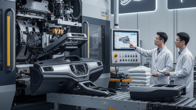
Automotive injection molding heats polymer pellets until they flow into a steel mold. Cooling then creates precise parts, such as dashboards, clips, ducts, and lighting housings. The method combines speed, repeatability, and low unit cost. PlasticsEurope’s Plastics—The Fast Facts 2023 report states that transport represented 8.6% of European plastics demand. The U.S. Department of Energy also reports that reducing vehicle weight by 10% can improve fuel economy by 6–8%.

Polypropylene remains common for trims, consoles, and battery-related components because it is light and chemically resistant. ABS offers a clean surface and useful impact strength. PC/ABS blends improve heat resistance and dimensional stability around instrument panels. Polyamide supports tougher parts near engines, while POM suits low-friction clips and mechanisms. TPU adds flexibility to seals and protective covers. Recycled polymers can reduce material demand, but their color, moisture, and strength may vary. Material selection is still a compromise.

Tips: Match the resin to heat, impact, and chemical exposure before designing the mold. Dry moisture-sensitive materials carefully; trapped water can create bubbles or weak weld lines. Use ribs instead of excessive wall thickness, but check shrinkage and warpage. A part may look perfect on paper and still fail during cooling. That is where production experience matters.

Key Materials Used in Automotive Injection Molding

This chart compares the representative density of common unfilled thermoplastic resins used in automotive injection molding. Polypropylene is lightweight and commonly used for interior and trim parts, while ABS, PA6, POM, and PC/ABS are selected when higher stiffness, wear resistance, dimensional stability, or impact performance is required. Actual values vary by grade, additives, reinforcement, and processing conditions.

How the Automotive Injection Molding Process Works

What Is Automotive Injection Molding and How Does It Work?

Automotive injection molding begins with a carefully designed mold and a selected thermoplastic material. Engineers study wall thickness, cooling paths, and expected vehicle loads before production starts. Small errors matter. A sharp corner can create stress, while uneven walls may cause warping. The mold is usually made from hardened steel or aluminum and contains the final component shape.

The process starts when plastic pellets enter a heated barrel. Rotating screws melt the pellets into a consistent, flowing material. The machine then injects the melt into the closed mold under controlled pressure. Sensors monitor temperature, pressure, and filling speed during this stage. After filling, holding pressure compensates for material shrinkage. Cooling channels remove heat until the part becomes stable enough to eject.

Ejector pins release the molded component without damaging its surface. Operators then inspect dimensions, appearance, and fit with nearby parts. Trimming, drilling, or surface treatment may follow. In real production, the first mold trial rarely performs perfectly. Engineers may adjust gate locations, cooling time, or injection speed after examining defects. This practical feedback improves repeatability, although excessive speed can still trap air or leave visible flow marks.

Major Applications in Vehicle Manufacturing

Automotive injection molding shapes molten polymer into repeatable vehicle components. Pellets enter a heated barrel and become a controlled melt. Injection pressure then fills a precision-machined mold. Cooling channels remove heat, and ejector pins release the finished part. The method suits high-volume production because one mold can repeat identical geometry thousands of times. It is not magic. Poor venting leaves burn marks, while uneven cooling creates warpage.

Major applications span cabin, body, chassis-adjacent, and powertrain areas. Engineers mold instrument-panel carriers, door trims, console parts, air vents, seat structures, and fastening clips. Exterior uses include grilles, mirror housings, wheel-arch liners, and lighting bezels.

Under the hood, glass-fiber-reinforced polymers can form covers, ducts, reservoirs, and electrical connectors. Battery-electric vehicles add sensor mounts, busbar carriers, and thermal-management housings.

The U.S. Department of Energy reports that a 10% vehicle weight reduction can improve fuel economy by 6–8%. This supports polymer substitution when heat and crash loads permit it.

Scale remains significant. The International Organization of Motor Vehicle Manufacturers recorded 93.5 million vehicles produced worldwide in 2023.

Such volume rewards automated molding, in-line vision inspection, and controlled material drying. ISO 20457 guides tolerances for molded plastic parts. However, a clean CAD model does not guarantee a reliable component. Gate location, weld lines, material variation, and tool wear still require hands-on validation.

Teams should test dimensions, impact performance, odor, and long-term aging before release.

Benefits and Manufacturing Considerations

Automotive injection molding shapes molten polymer inside a precision mold under controlled pressure. It produces dashboards, clips, housings, grilles, and interior structural parts in high volumes. A heated barrel melts plastic pellets, then a screw pushes the material through a gate into the cavity. After cooling, ejector pins release the part. The cycle can take only seconds.

The main benefits are speed, repeatability, and lower unit costs at scale. One mold can create several parts during each cycle. That supports consistent assembly and reduces secondary machining. Plastic also offers low weight, corrosion resistance, and design freedom. Engineers can combine ribs, snap fits, and textured surfaces in one component. Less hardware may be needed. However, these savings depend heavily on production volume and tool life.

Manufacturing decisions must begin before the mold is cut. Wall thickness, draft angles, gate location, and cooling channels influence quality and cycle time. A design that looks perfect on screen may warp after molding. Uneven cooling can create sink marks, weld lines, or visible distortion. Material selection also requires testing for heat, impact, chemicals, and long-term aging. Recycled content may reduce environmental impact, but it can affect color, strength, and consistency. Mold trials, dimensional checks, and real assembly tests reveal problems early. Some teams still underestimate these steps. That mistake can make a fast process expensive.

What Is Automotive Injection Molding and How Does It Work? — Benefits and Manufacturing Considerations
Category Dimension Typical Data or Range Manufacturing Relevance
Process Basic operating sequence Material is melted, injected into a closed mold, packed, cooled, and ejected. Repeatable automation makes the process suitable for high-volume automotive production.
Materials Common thermoplastics Polypropylene (PP), acrylonitrile butadiene styrene (ABS), polyamide (PA), polycarbonate (PC), polyoxymethylene (POM), and thermoplastic elastomers (TPE). Material selection depends on strength, temperature resistance, chemical exposure, surface finish, flexibility, and cost.
Automotive applications Typical molded components Instrument-panel components, interior trim, air-vent parts, clips, brackets, housings, bezels, handles, under-hood covers, and fluid-system components. The process supports both visible aesthetic parts and functional structural or protective components.
Production volume Best-fit production level Medium- to high-volume production, particularly when tooling costs can be spread across many parts. Unit cost generally decreases as production volume increases, while the mold remains a major upfront investment.
Cycle time Typical molding cycle Often measured in seconds; the actual cycle depends on part thickness, material, mold design, cooling efficiency, and machine settings. Cooling is frequently the longest stage, so efficient cooling channels can improve productivity and dimensional consistency.
Part thickness Wall design reference Many automotive plastic parts use relatively thin, uniform walls; the practical range varies by resin, flow length, geometry, and performance requirements. Uniform wall thickness helps reduce sink marks, warpage, air entrapment, and uneven cooling.
Dimensional control Typical design expectation General molded-part tolerances are commonly specified around ±0.1 to ±0.3 mm for selected dimensions, but tighter or looser values may be required. Tolerance depends on material shrinkage, feature size, mold accuracy, process stability, and inspection method.
Material shrinkage Common unfilled-plastic reference Approximately 0.5%–2.0% for many unfilled thermoplastics; the exact value varies by resin, flow direction, packing, and mold temperature. Mold dimensions must compensate for expected shrinkage to achieve the required final part size.
Clamping force Machine-sizing factor Selected from projected part area, cavity pressure, material behavior, mold layout, and a safety margin rather than part weight alone. Insufficient clamping force can cause flash; excessive force may increase machine and mold wear.
Tooling Mold construction A mold normally includes a cavity, core, runners, gates, cooling channels, vents, and an ejection system. Gate location, venting, cooling, and ejection layout strongly influence appearance, cycle time, and part quality.
Design features Design-for-manufacturing guidelines Use draft angles, radiused corners, ribs, bosses, consistent walls, appropriate openings, and accessible ejection surfaces. These features improve mold release, stiffness, filling behavior, and tool life while reducing defects.
Surface finish Available finish options Polished, textured, matte, or grain-like finishes can be produced directly through the mold surface. Surface texture affects appearance, glare, scratch visibility, part release, and perceived quality.
Secondary operations Post-molding processes Possible operations include trimming, drilling, welding, coating, printing, assembly, insert installation, and quality inspection. Reducing secondary operations through integrated features can lower labor, handling, and assembly costs.
Key benefits Production advantages High repeatability, complex geometry, low labor per part at scale, integrated functional features, and consistent surface appearance. These advantages support lightweighting, design flexibility, and efficient mass production.
Main risks Common quality issues Short shots, flash, sink marks, weld lines, warpage, burn marks, voids, splay, and dimensional variation. Stable material drying, mold temperature, injection speed, packing pressure, cooling, and inspection controls help prevent defects.