Injection Molding Motorcycle Parts requires more than choosing a resin and pressing a cycle-start button. Every part must balance strength, weight, appearance, cost, and repeatability. A mirror housing, battery cover, or airbox may look simple, yet each contains hidden design decisions. Wall thickness, draft angles, ribs, gates, cooling channels, and tolerances all influence final performance.
Industry data shows why material discipline matters. PlasticsEurope’s Plastics—The Facts 2023 reported global plastics production of 400.3 million tonnes in 2022. That scale supports extensive material development, but it also highlights a problem: not every polymer suits vibration, heat, fuel exposure, or ultraviolet aging. Motorcycle components face road dust, engine warmth, rain, and repeated impacts. Small weaknesses become visible quickly. Very quickly.
This guide presents ten practical tips for Injection Molding Motorcycle Parts, based on proven mold-design principles and production experience. Reports from Grand View Research and MarketsandMarkets continue to identify automation, lightweighting, and advanced polymers as major manufacturing trends. However, market growth does not guarantee part quality. A polished CAD model can still produce sink marks, warpage, weld lines, or difficult ejection. I have also seen teams overfocus on cycle time while ignoring service access and real-world assembly. That is an expensive lesson. Good engineering reviews material data, mold-flow results, prototype feedback, and supplier capability together. The aim is not merely to make attractive plastic parts. It is to create durable, repeatable components that perform reliably after thousands of kilometres.
Define the performance requirements before designing a motorcycle part for injection molding. Record temperature, impact, vibration, chemical exposure, and service life. A body panel may face sunlight and fuel vapor, while a connector housing needs dimensional stability and electrical safety. PlasticsEurope’s Plastics—The Fast Facts 2023 reports 400.3 million tonnes of global plastics production in 2022. That scale makes material selection and responsible waste planning important. Do not choose resin from habit.
Tip: Convert riding conditions into measurable limits. Specify a continuous temperature range, peak impact energy, allowable deflection, and color-change tolerance. Test tensile strength under ASTM D638 and heat deflection under ASTM D648. For a practical check, inspect a molded cover after thermal cycling, vibration, and chemical wiping. Small stress marks around screw bosses often reveal weak requirements.
Tip: Define the failure that matters most. A flexible guard may tolerate scratches but must not crack during a low-speed impact. A structural bracket needs stiffness, fatigue resistance, and controlled deformation. ISO 527 tensile data and ISO 178 flexural data can support material comparisons, but laboratory values are not road performance. A perfect requirement sheet is rarely perfect. Real testing may expose an overlooked fastening load or an unrealistic wall thickness.
Tip: Set production targets early. Record shrinkage limits, flatness, weld-line strength, and acceptable flash. Include recycled-content goals only after confirming impact and heat performance. The detail may feel excessive, yet unclear limits create costly tooling changes later.
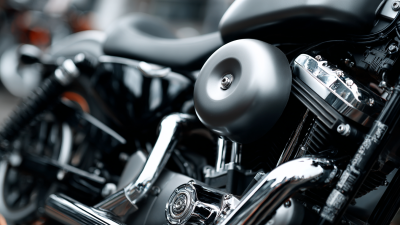
Motorcycle parts face vibration, heat, rain, fuel exposure, and repeated impact. Material selection must match the part’s real environment, not only its appearance. Polypropylene suits lightweight covers and flexible guards. ABS can provide a clean surface for visible trim, but prolonged sunlight may require stabilization. Nylon offers strength for brackets and housings, while moisture can change its dimensions. POM works well for low-friction clips and moving components, although it needs careful processing control.
Glass-filled materials can improve stiffness, yet they may increase warpage and create a rougher surface. Designers should consider fiber direction near mounting holes and thin ribs. For outdoor parts, ultraviolet resistance matters. For parts near engines, heat aging and dimensional stability deserve more attention. Recycled content can reduce environmental impact, but its consistency must be verified between batches. This is often underestimated.
Strength begins with a stable wall thickness, not excessive plastic. Keep core walls consistent, then add ribs where loads travel. Ribs near mounting points should stay about 40 to 60 percent of the wall thickness. Use generous radii at corners. Sharp internal edges invite stress and difficult filling. Add draft to every draw surface. One degree may work, but deeper textures often need more.
Fit depends on disciplined reference geometry. Define datums before setting holes, slots, and mating faces. Do not hold every dimension tightly. Reserve close tolerances for functional interfaces, and confirm them after cooling. Bosses need support ribs and suitable wall thickness. Otherwise, screws can create sink marks or cracks. Place the gate away from visible and highly loaded areas. Flow simulation helps, though it cannot replace molded trials.
Manufacturability is often where attractive designs fail. Balance cooling paths around thick sections to reduce warpage. Keep ejector locations clear of sealing surfaces and cosmetic zones. Shorten deep cores when possible. In production reviews, I have seen small draft changes prevent costly tooling changes. A perfect first draft is unlikely. Prototype the part, measure critical fits, and test vibration, heat, and repeated loads. Record the results, revise the model, and question assumptions.
Configure molds and process parameters before chasing cosmetic defects. For motorcycle parts, balance gate location, wall thickness, draft angles, and ejector placement. A gate near a thick rib can reduce sink marks, but it may create an unwanted weld line. Design cooling channels close to the cavity surface, with even spacing around corners. SPE technical literature places cooling at roughly half to two-thirds of many molding cycles, so poor cooling quickly becomes expensive. Check coolant flow, mold temperature, and cavity pressure, not only the machine display.
Dry moisture-sensitive resin to the supplier’s specified dew point and time. Set barrel zones gradually. Excessive heat can hide moisture problems, then produce brittle parts later. Use a staged fill profile, with slower speed near the final 10% of filling. Set switchover by screw position or cavity pressure, rather than time alone. Confirm pack pressure and hold time by observing gate freeze. Calculate clamp force from projected area and cavity pressure, then leave a sensible safety margin. ISO 20457:2018 provides a useful framework for molded-part tolerances and acceptance conditions. Record part weight, cycle time, mold temperature, and first-piece dimensions every run. DOE’s Manufacturing Energy and Carbon Footprint data identifies motor-driven systems and process heating as major factory energy loads; stable cycles also reduce wasted energy.
“ I still distrust a perfect first-off sample. Run a short capability study across at least 30 consecutive shots. Inspect critical holes, clips, and mounting faces. If variation appears, adjust one parameter at a time. Mold wear, blocked vents, and uneven cooling are easy to blame on “material.” That assumption deserves another look.
A molded motorcycle component can look perfect and still fail during assembly. Inspect each finished part under bright, angled light. Check flash, sink marks, short shots, burn marks, and uneven texture. Measure critical dimensions with calibrated calipers or gauges. Compare mounting holes, ribs, clips, and sealing surfaces with the approved drawing.
Looks are deceptive. Test the part in a real assembly whenever possible. Check fastener fit, panel alignment, connector clearance, and movement near heat sources. Apply controlled vibration and repeated installation cycles to expose weak clips or stressed corners. For parts near engines or road spray, use temperature, moisture, and chemical-resistance tests that match actual service conditions. Record every result.
Refinement should follow evidence, not assumptions. A small warp may come from uneven cooling, excessive packing pressure, or an unbalanced gate layout. Adjust one process variable at a time, then inspect a fresh sample. Our early checklist missed a thin rib that cracked after repeated flexing. That mistake changed our review process. We now inspect hidden sections and test parts after conditioning, not only directly after molding. Some defects remain difficult to reproduce. Retain failed samples, photographs, measurements, and machine settings for traceable decisions. Recheck the component after each tooling or material change.
First-pass acceptance rates from a representative 100-component quality audit. Visual, dimensional, fit, functional, and environmental checks help identify defects before motorcycle parts reach assembly.
The largest improvement opportunity is environmental testing, where temperature cycling and impact exposure can reveal warpage, cracking, brittleness, or loss of fit. Refining mold settings, cooling time, material drying, and gate locations can improve first-pass results.