Leave Your Message

Why Choose Injection Molding for Automotive Parts?

Automotive parts must do more than fit. They face vibration, temperature swings, road debris, and years of repeated use. Injection Molding Automotive Parts offers manufacturers a way to produce complex components with consistent dimensions and repeatable cycle times. A molded connector housing, for example, can combine ribs, clips, and mounting points in one part. That may reduce assembly steps and help control production costs.

Material and tool choices matter. A dashboard bracket may need stiffness and heat resistance, while a flexible seal requires different properties. As a transparent paraphrase of principles discussed in John Beaumont’s injection-molding publications: “Design, material, and process should be developed together.” That is not a verbatim quotation. It reflects a practical point: a strong mold cannot rescue a poorly designed part, and a suitable resin still needs controlled processing. Small changes in wall thickness or gate location can affect filling, cooling, warpage, and visible surface quality.

The benefits are real, but not automatic. Tooling can demand substantial upfront investment, and design changes become costly after a mold is built. Mold-flow analysis, prototype testing, and careful inspection can reduce avoidable surprises. Still, simulations are not the factory floor. Real production can reveal issues that models miss. This guide examines why automotive manufacturers choose injection molding, where it performs well, and what teams should verify before committing to a design.
Why Choose Injection Molding for Automotive Parts?

How Injection Molding Produces Automotive Parts

Automotive injection molding begins with resin pellets, often dried before heating. A screw melts and blends the material, then pushes it into a closed metal mold. The cavity shapes the part under pressure. Small details matter. Ribs add stiffness; molded bosses provide mounting points for screws. After cooling, the mold opens and ejector pins release the part. The cycle repeats, but stable results depend on careful control of temperature, pressure, and cooling time.

The American Chemistry Council’s 2019 report on plastics and polymer composites in light vehicles estimates these materials account for about 10% of vehicle weight and nearly half its volume. That helps explain their use in dashboards, trim, and housings. U.S. Department of Energy guidance estimates that reducing vehicle weight by 10% can improve fuel economy by 6–8%; this is a general lightweighting estimate, not a promise for any molded part. Still, injection molding is not magic. Uneven cooling can warp a panel, while poor gate placement may leave a visible mark. There is a trade-off here, and it is easy to underestimate: designers must balance part strength, appearance, material use, and cycle time. A small trial run can reveal problems that a computer model misses.

Key Material and Design Requirements for Automotive Components

Automotive components face heat, vibration, moisture, and repeated handling. Material selection should reflect the part’s actual location and job, not just its purchase price. Under-hood parts may need to retain strength at elevated temperatures, while interior trim often prioritizes impact resistance, surface quality, and low odor. Polypropylene can suit lighter-duty housings; reinforced nylon or polyester may be considered where greater stiffness is needed. Check chemical exposure, too. Oils and cleaners can change performance.

Design details influence whether a material can be molded consistently. Keep wall thickness as uniform as practical to reduce sink marks and uneven cooling. Add draft to vertical faces so parts release cleanly from the mold. Rounded corners, rather than sharp internal edges, help reduce stress concentrations. Ribs can add stiffness without making the whole wall thick, but oversized ribs may leave visible marks. Small details matter.

Fiber reinforcement can improve stiffness, yet it may also increase directional shrinkage and warpage. Gate position and weld lines deserve attention, especially near clips, screw bosses, or load-bearing areas. Set tolerances around function and process capability; demanding precision everywhere can raise costs without improving performance. Real parts are messier. A CAD model may look sound, but prototypes and molding trials can reveal fit issues, weak snap-fits, or cosmetic flaws that need another design pass.

Why Choose Injection Molding for Automotive Parts? — Key Material and Design Requirements for Automotive Components
Material / Design Factor Typical Automotive Applications Typical Properties or Guideline Key Selection and Design Requirements
Polypropylene (PP) Interior trim, clips, air ducts, reservoirs, and selected exterior trim Density: approximately 0.90–0.91 g/cm³; tensile strength: typically about 25–35 MPa for unfilled grades Low density and good chemical resistance make PP useful for lightweight parts. Account for shrinkage and warpage, especially in large panels, and check impact performance at the expected service temperature.
Polyamide 6, 30% glass-fiber reinforced (PA6-GF30) Brackets, housings, structural supports, and under-hood components Density: approximately 1.35–1.40 g/cm³; tensile strength is often about 150–200 MPa in dry, molded test specimens High stiffness and strength suit load-bearing parts. Moisture changes dimensions and mechanical properties, so specify conditioning requirements and design for fiber orientation, weld lines, and anisotropic shrinkage.
Polybutylene terephthalate, 30% glass-fiber reinforced (PBT-GF30) Electrical connectors, sensor housings, and under-hood electrical components Density: approximately 1.50–1.55 g/cm³; tensile strength commonly falls around 120–160 MPa, depending on grade and test conditions Useful for dimensional stability and electrical applications. Confirm the selected grade’s heat, chemical, and hydrolysis resistance for the environment; provide suitable venting and manage glass-fiber orientation.
Polycarbonate / acrylonitrile-butadiene-styrene blend (PC/ABS) Instrument-panel components, console parts, bezels, and interior housings Density: approximately 1.10–1.20 g/cm³; tensile strength is commonly about 40–65 MPa Offers a balance of impact resistance, appearance, and processability. Check the grade’s heat and chemical resistance, and use consistent wall thickness to reduce sink marks and visible surface defects.
Polyoxymethylene (POM / acetal) Gears, bushings, latches, and sliding or snap-fit mechanisms Density: approximately 1.41–1.43 g/cm³; tensile strength is typically about 60–70 MPa for common unfilled grades Low friction and good dimensional stability support moving components. Design for the material’s shrinkage, avoid sharp internal corners, and verify compatibility with fuels, lubricants, and other service fluids.
Wall thickness Applies across molded automotive components A starting range of roughly 2–4 mm is common for many thermoplastic parts; the suitable value depends on material, geometry, and performance needs Keep walls as uniform as practical. Thick-to-thin transitions can cause sink, voids, and uneven cooling; use gradual transitions where changes in section are necessary.
Ribs and bosses Reinforcement features, screw locations, and mounting points A common starting point is rib thickness around 50–60% of the adjoining nominal wall, subject to material and surface requirements Use ribs to add stiffness instead of making the whole wall thicker. Keep ribs reasonably slender, use radiused roots, and avoid placing heavy bosses directly behind appearance surfaces.
Draft and mold release All molded parts, especially deep walls and textured surfaces About 1–2° draft per side is a common starting point for smooth walls; textured surfaces often need more Confirm draft with the toolmaker based on texture, depth, resin, and ejection direction. Adequate draft helps release parts and reduces scuffing, sticking, and ejection stress.
Why injection molding is chosen Repeatable production of clips, housings, trim, connectors, and other high-volume parts Supports complex geometry, integrated features, repeatable dimensions, and efficient production at scale Design parts with the molding process in mind: provide a workable parting line, gate and ejector locations, venting, and access for tooling. Validate material performance and dimensional tolerances under real service conditions.

Note: Property figures are indicative ranges for common material grades, not guaranteed specifications. Actual values vary by grade, reinforcement, moisture condition, molding process, specimen preparation, and test method. Confirm requirements with the selected material supplier and applicable automotive specifications.

Benefits of Injection Molding in Automotive Manufacturing

Injection molding supports repeatable production of automotive components with detailed shapes and consistent dimensions. That matters for clips, housings, air ducts, and interior trim. Small features can be molded directly, reducing secondary machining and assembly steps. Less handling. Well-designed parts can combine ribs, bosses, and fastening points without adding separate pieces. This can help reduce mass, an important goal in vehicle design.

The process also suits high-volume manufacturing. Once a mold is validated, automated cycles can produce many parts with stable geometry and surface finish. Material choice matters: heat, vibration, chemicals, and impact all affect performance. Engineers can test molded samples under conditions that resemble actual use instead of relying on data sheets alone. Tooling is expensive, though. Changes after the mold is cut can be slow and costly, so early design reviews are valuable. The process is not flawless. Gate marks, weld lines, or uneven cooling may still appear, and they need practical inspection criteria. For lower volumes, another process may make more sense.

Common Automotive Parts Made by Injection Molding

Why Choose Injection Molding for Automotive Parts?

Common Automotive Parts Made by Injection Molding

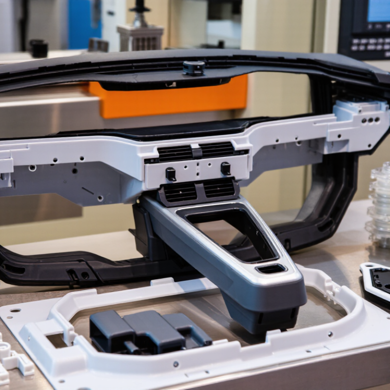
Automotive injection molding produces many everyday components: dashboard panels, air vents, console bins, door-trim pieces, clips, and wire guides. Small parts matter. Under the hood, molded connectors and covers must tolerate heat, vibration, and contact with fluids. Material choice depends on the part’s location and job; a cabin trim piece faces different conditions from an engine-bay component.

OICA’s 2023 Production Statistics recorded 93,546,599 motor vehicles produced worldwide. That scale helps explain the value of repeatable, high-volume manufacturing, but it does not mean every part should be molded. Injection molding can form complex shapes and fine details in one cycle. It can also reduce assembly steps when clips or ribs are built into a component. Still, a polished prototype may warp after cooling. Wall thickness, gate placement, and material testing deserve attention before tooling is finalized.

Factors to Consider When Selecting Injection Molding

Why Choose Injection Molding for Automotive Parts?

Factors to Consider When Selecting Injection Molding

Selecting injection molding starts with the part’s job, not just its shape. A dashboard clip, an under-hood housing, and a seat component face different loads and temperatures. Define expected production volume, service life, and exposure to fluids before comparing processes. Volume matters. Tooling can be costly, so estimate whether repeat production will justify the initial investment. A low-volume prototype may need a different route.

Material choice affects strength, weight, heat resistance, and dimensional stability. Check the part’s operating temperature and contact with oils or cleaning agents. Ask suppliers for material data and test parts under realistic conditions; a specification sheet alone cannot reveal every failure mode. Heat changes things. For tight-fitting parts, review shrinkage, tolerances, and the location of gates and weld lines. These details can influence fit and appearance.

Design for moldability early. Consistent wall thickness, sensible draft angles, and accessible geometry can reduce defects and simplify ejection. Undercuts may require more complex tooling, so assess whether they are essential. A CAD model is not proof. I would keep early cost estimates provisional: cooling layout, cycle time, and scrap rates can shift the numbers. Validate samples with dimensional checks and assembly trials before committing to production.